Einbauanleitung für Yamaha Ebike-Motoren
Yamaha PW-SE, PW-ST, PW-X, PW-X2 oder PW-TE Antrieb:
Vor der Arbeit am Fahrrad den Akku entfernen!
1. Entfernen Sie die untere Steinschlagschutzabdeckung. Diese wird von 4 Inbus-Schrauben Größe 4 gehalten.
2. Lösen und entfernen Sie auf der Seite mit dem Kettenblatt die gezeigte Befestigungsschraube mit einem 5mm Inbus. Im Kettenblatt gibt es eine Aussparung, mit der die Schraube mit einem Kugelkopf-Inbus schräg erreicht werden kann. Die Schraube nur leicht lösen, sie dient als Scharnier!
3. Lösen Sie die gezeigte Schraube mit einem Inbus
4. Lösen und entfernen Sie die Schraube 1 mit einem Inbus Größe 6. Lösen Sie dann die Schraube 2 leicht. Diese dient ebenfalls als Scharnier, um den Motor herunterzuklappen.
5. Klappen Sie den Motor herunter. Gehen Sie dabei vorsichtig vor. Es kann sein, dass er sich etwas verkantet. Bitte achten Sie darauf keine Kabel abzureißen oder zu quetschen.
6. Trennen Sie die 5-polige Steckverbindung (1). Diese ist im Rahmenrohr nach oben verstaut. Die weiße Verriegelung kann mit dem Fingernagel oder einem kleinen Schlitz-Schraubendreher geöffnet werden. Diese bleibt dann in der geöffneten Position (siehe nächstes Bild).
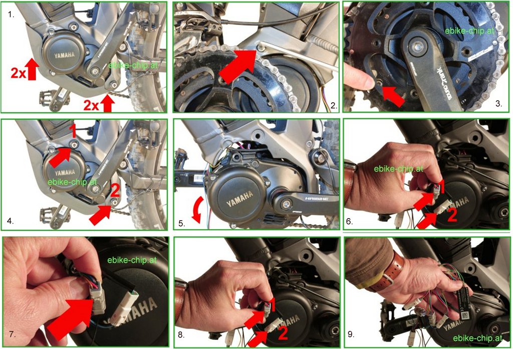
7. Die geöffnete Verriegelung. In dieser Stellung können die Stecker einfach getrennt werden.
8. Trennen Sie die 3-polige Steckverbindung (2). Diese ist im Rahmenrohr nach oben verstaut. Die Verriegelung kann am
Pfeil ebenfalls mit dem Fingernagel oder einem kleinen Schlitzschraubendreher gelöst werden.
9. Verbinden Sie die 4 Steckverbinder des Moduls mit den eben gelösten Steckverbindern am Rad. Achten Sie darauf, dass alle Steckverbinder ordnungsgemäß einrasten.
10. Verstauen Sie das Tuning sowie alle Steckverbinder und Kabel im Rahmenrohr.
11. Klappen Sie den Motor wieder vorsichtig nach oben in seine Position. Achten Sie darauf keine Kabel zu quetschen
oder zu verletzen. Der Motor kann dann mit der vorhin entfernten Schraube in Position gehalten werden. Schrauben Sie den Motor in umgekehrter Reihenfolge wieder fest. Achten Sie beim Festziehen der Motorschrauben auf das vorgeschriebene Drehmoment des Herstellers.
Aktivierung vom Tuning:
Um die Unterstützung oberhalb von 25km/h an- oder abzuschalten, wechseln Sie bitte die Unterstützungsstufe um eine Stufe runter, hoch, runter und wieder hoch.
Ein Beispiel, beginnend in der Stufe Std:
Taster runter (neue Stufe: Eco)
Taste hoch (neue Stufe: Std)
Taste runter (neue Stufe: Eco)
Taste hoch (neue Stufe: Std)
Eine Animation über die Kapazitäts-Anzeige des Akkus im Display zeigt an, ob das Tuning aktiviert oder deaktiviert ist. Läuft die Kapazität von leer auf voll, unterstützt Sie Ihr Pedelec auch mit Motorleistung, wenn Sie schneller als 25 km/h fahren. Läuft die Anzeige von voll auf leer, endet die Unterstützung des Motors bei 25 km/h.
Yamaha Syncdrive Antrieb (ab 2017):
1. Entfernen Sie den Akku, indem Sie den Schlüssel drehen und den Akku heraus klappen
2. Lösen Sie die 4 Schrauben der Akku-Halterung mit einem Inbus Schlüssel.
3. Um die Seitenverkleidungsteile zu lösen oder abzunehmen, müssen Sie vorher die Akku-Halterung vorsichtig anheben. Es müssen die zwei Laschen nach oben aus den Seitenverkleidungsteilen herausgeschoben werden. Achten Sie darauf keine Kabel abzureißen!
4. Lösen und entfernen Sie die 3 gezeigten Schrauben der rechten Motorabdeckung und des Unterfahrschutz mit einem passenden Inbus.
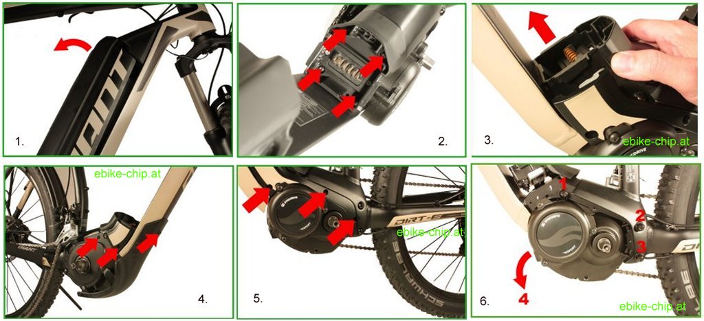
5. Lösen und entfernen Sie die 3 Schrauben der linken Motorabdeckung mit einem passenden Inbus. Entfernen Sie danach die Abdeckung. Die Abdeckung kann über die Kurbel gestülpt werden.
6. Lösen und entfernen Sie die vorderen beiden Motorschrauben (1+2) mit einem passenden Inbus. Achtung: Die Schrauben können unterschiedlich lang sein! Beachten Sie dies beim Zusammenbau! Lösen Sie dann die dritte Schraube (3), und nutzen Sie diese später als Scharnier, um den Motor herunterzuklappen.
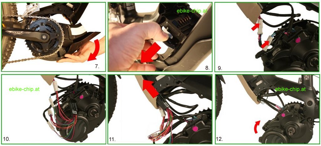
7. Lösen und entfernen Sie die vorderen beiden Motorschrauben (1 + 2) mit einem passenden Inbus. Achtung: Die Schrauben
können unterschiedlich lang sein! Beachten Sie dies beim Zusammenbau!
Halten Sie den Motor zunächst in Position und beachten den nächsten Schritt!
8. Biegen Sie die rechte Seitenverkleidung vorsichtig etwas weg vom Rahmen. Der Motor kann dann heruntergekippt werden.
9. Lösen Sie die weiße 8-polige und weiße 3-polige Steckverbindung am Motor. Sollten Sie die Stecker nicht direkt finden, folgen Sie bitte den Kabeln im Rahmen. Die Steckerbinder sind mit einer Rastnase gesichert. Drücken Sie diese vorsichtig. (z.B. mit einem schmalen Schlitzschraubendreher, siehe rote Pfeile)
10. Verbinden Sie die 4 Steckverbinder des Moduls mit den entsprechenden Gegenstücken der eben gelösten Verbindungen.
Bitte verwenden Sie ausschließlich die weißen Steckverbinder!
Sollten Sie den 3-poligen weißen Steckverbinder nicht finden, folgen Sie dem Kabel vom Geschwindigkeitssensor am Hinterrad.
11. Verstauen Sie das Modul, die Steckverbinder und die Kabel im Rahmenrohr.
12. Klappen Sie den Motor wieder nach oben und achten Sie darauf, dass keine Kabel gequetscht werden. Befestigen Sie den Motor wieder mit den vorhin gelösten Schrauben.
13. Montieren Sie den Motor, die Abdeckungen, das Kettenblatt, die Tretkurbeln und die Akku-Halterung wieder in umgekehrter Reihenfolge.
Bitte achten Sie bei den Motorschrauben auf das vorgeschriebene Drehmoment des Herstellers (in der Regel 20Nm; Angabe ohne Gewähr). Bitte achten Sie bei der Kettenblattmutter auf das vorgeschriebene Drehmoment des Herstellers (in der Regel 40Nm; Angabe ohne Gewähr)
Häufige Fehlerursache
Symtom: Man hat keine bzw. nur kurz eine Motorunterstützung und es wird keine Geschwindigkeit angezeigt.
Lösung: Bitte überprüfen Sie die 3-poligen Steckverbinder vom Modul zum Motor und zum Geschwindigkeits-Sensor. Dieser muss mit den weißen Gegenstücken verbunden sein, nicht mit den roten!
Aktivierung
Um die Unterstützung oberhalb von 25km/h an- oder abzuschalten, wechseln Sie bitte die Unterstützungsstufe um eine Stufe runter, hoch, runter und wieder hoch. Bei Erfolg sehen Sie die Animation der Trip-Time Anzeige wie beim Einschalten Ihres Pedelecs, die dadurch über den aktuellen Zustand informiert.
Ein Beispiel, beginnend in der Stufe Normal:
Taster runter (neue Stufe: Eco)
Taste hoch (neue Stufe: Normal)
Taste runter (neue Stufe: Eco)
Taste hoch (neue Stufe: Normal)
Bei der Trip-Time-Animation wird innerhalb von ca. 3 Sekunden die Ziffer 1 auf dem Display angezeigt. Läuft die Anzeige von 00:00 auf 11:11, unterstützt Sie Ihr Pedelec auch mit Motorleistung, wenn Sie schneller als 25 km/h fahren. Läuft die Anzeige andersherum, endet die Unterstützung des Motors bei 25 km/h.
Zeigt die Animation der Tacho-Anzeige innerhalb von ca. 3 Sekunden die Geschwindigkeit steigend von 3 auf 7 km/h an, unterstützt Sie Ihr Pedelec auch mit Motorleistung, wenn Sie schneller als 25 km/h fahren. Läuft die Anzeige andersherum, endet die Unterstützung des Motors bei 25 km/h.
Das Modul bleibt in den jeweiligen Zustand, bis die Tastenkombination wieder gedrückt wird. Auch nach dem Ein-/Ausschalten vom Ebike.
Yamaha Syncdrive Pro2 oder PW-X3 Motoren ab Motorjahr 2022
1. Öffnen Sie den Verschluss der Akku-Abdeckung und entfernen Sie diese dann. Die Abdeckung wird an den Seiten noch mit Kunststoffclips gehalten.
2. Lösen Sie die Befestigungsschraube des Akkus mit einem Torx T25 oder Ihrem Schlüssel. Hinweis: Es handelt sich um eine Endlosschraube, die nicht entfernt werden kann. Halten Sie den Akku fest, damit er nicht herausfallen kann und Entriegeln Sie dann den Akku mit dem Fallschutzhebel oben am Akku und entnehmen diesen.
3. Lösen Sie die Befestigungsschraube der linken Tretkurbel mit einem Inbus Größe 8. Die Schraube funktioniert gleichzeitig als Kurbelabzieher. Drehen Sie diese so lange bis Sie die Kurbel abnehmen können.
4. Lösen Sie die vier Schrauben des unteren Steinschlagschutzes mit einem Inbus Größe 2,5 und nehmen Sie diesen ab. Hinweis: Es werden vorne und hinten unterschiedliche Schrauben verwendet. Bitte merken Sie sich die Position für die spätere korrekte Montage.
5. Ziehen Sie die beiden Steckverbinder für das Display (6-polig, beschriftet mit „Info“) und den Geschwindigkeitssensor (3-polig, beschriftet mit „SS“) ab. Die Stecker werden mit einer Rastnase gehalten. Diese lösen Sie einfach mit einem leichten Druck mit dem Fingernagel oder einem schmalen Schraubendreher.
6. Lösen Sie die drei Schrauben der seitlichen Abdeckung. (Schraube 1 mit einem Inbus Größe 2,5, Schrauben 2 und 3 mit einem Inbus Größe 2,0) Nehmen Sie dann die seitliche Abdeckung ab.
Hinweis: Schraube 1 ist baugleich, aber länger als die Schrauben für die untere Steinschlagschutzabdeckung. Bitte nicht verwechseln!
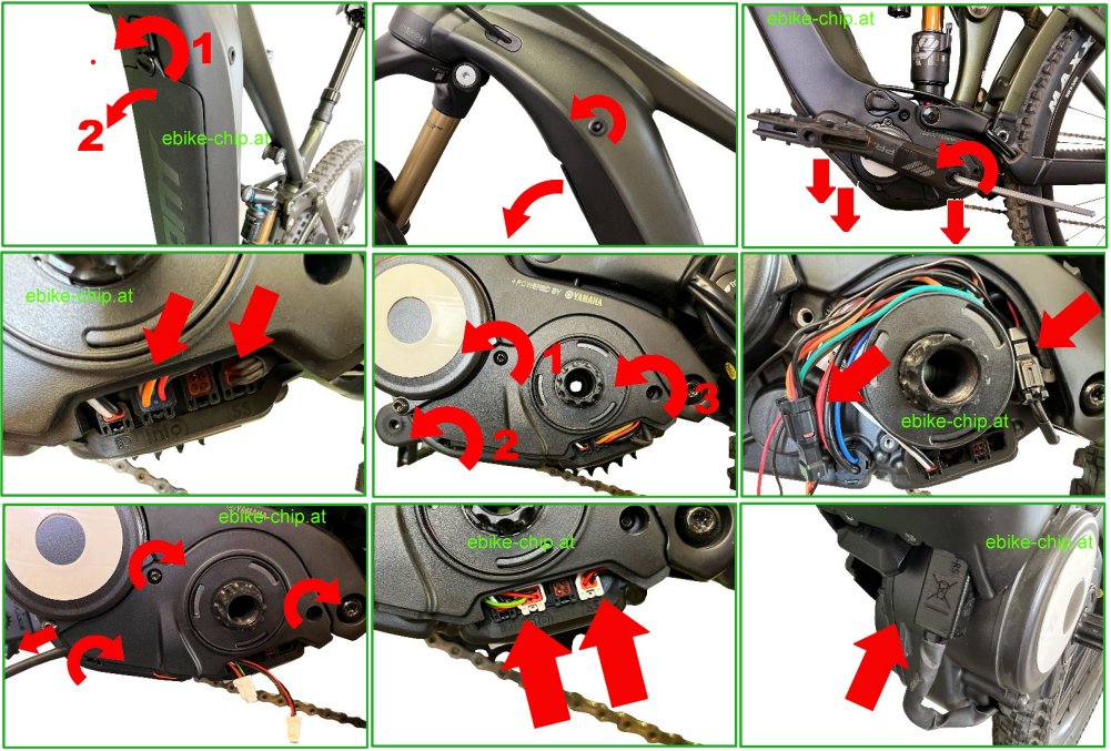
7. Verbinden Sie die beiden in Schritt 5 abgezogenen Steckverbinder mit den entsprechenden Gegenstücken vom Modul und platzieren Sie die Steckverbindungen an den mit Pfeilen markierten Stellen.
8. Bringen Sie die seitliche Abdeckung wieder an. Führen Sie dabei die zwei übrigen Steckverbinder des Moduls aus der Öffnung unten rechts und führen Sie das Kabel zum Modul links aus der Abdeckung. (siehe Pfeil) Befestigen Sie die dann die Abdeckung wieder mit den drei Schrauben. Achten Sie darauf keine Kabel zu quetschen!
9. Verbinden Sie die beiden Steckverbinder des Moduls mit den Steckplätzen am Motor, wo Sie in Schritt 5 die originalen Steckverbinder abgezogen haben.
10. Verstauen Sie den Chip an der gezeigten Stelle im Rahmen.
11. Bringen Sie die untere Steinschlagschutzabdeckung wieder an und befestigen Sie diese mit den vier Schrauben. Achten Sie dabei darauf die korrekten Schrauben vorne und hinten zu verwenden. (siehe Hinweis von Schritt 4)
Montieren Sie die Tretkurbel. Diese dazu einfach ansetzen und die Schraube mit einem Inbus Größe 8 festziehen. Dabei zieht sich die Kurbel auf die Achse und wird gleichzeitig festgeschraubt.
Setzen Sie den Akku ein und befestigen Sie diesen mit der gelösten Halteschraube oder Ihrem Schlüssel (siehe Bedienungsanleitung zu Ihrem Fahrrad). Schließen die Akku-Abdeckung und befestigen diese wieder mit den seitlichen Clips und der Halteschraube.