Einbauanleitung für Sachs-RS Ebike-Motoren
1. Bitte schalten Sie das Rad aus und entfernen den Akku aus dem Rahmen. Dann entfernen Sie die gezeigte Abdeckung am Motor durch Lösen der 3 Schrauben. Darunter finden Sie diverse Steckverbinder zum Motor.
2. Ziehen Sie am besten alle Steckverbinder am Motor ab, um sich etwas Platz für die nächsten Schritte zu schaffen. Die Stecker sind codiert und können später nicht falsch wieder eingesteckt werden. Sie können aber auch ein Foto machen, um sich an die Position zu erinnern.
3. Lösen Sie die untere Akku-Halterung durch Entfernen der 4 gezeigten Schrauben. Bitte beachten Sie, dass die Halterung mit Kabeln verbunden ist. Vermeiden Sie es, an diesen zu ziehen.
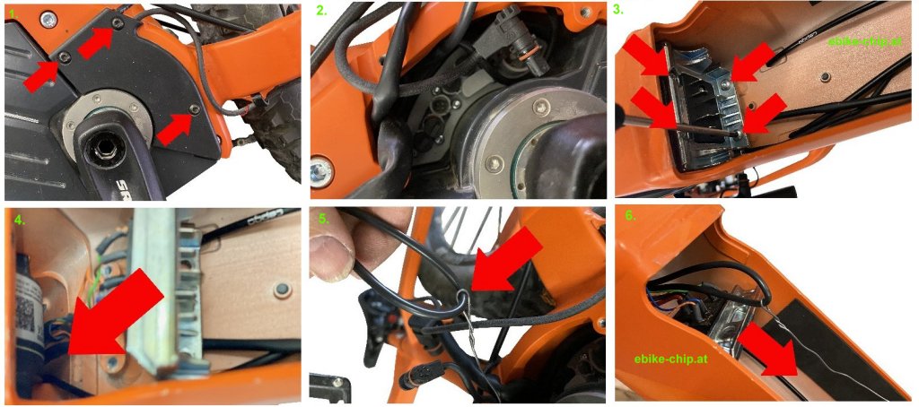
4. Fädeln Sie einen Zugdraht oder Kabelbinder unter dem Motor durch. Beginnen Sie damit hinter der gerade entfernten Halterung für den Akku. Das Ziel des Zugdrahts ist die Öffnung der in Schritt 1 entfernten Abdeckung.
5. Binden Sie das mitgelieferte ca. 1m lange Kabel an den Zugdraht. Es empfiehlt sich zuerst eine Schlaufe dieses Kabels unter dem Motor durch zu ziehen. (siehe nächster Schritt). Der schwarze 4- polige Steckverbinder muss in den Akku-Schacht, das Ende mit den zwei 3-poligen Steckverbindern bleibt aus der Öffnung von Schritt 1.
6. Wenn Sie die Schlaufe des Kabels unter dem Motor durchgezogen haben, ziehen Sie danach vorsichtig das Ende mit dem 4-poligen Steckverbinder nach. Im Akku-Schacht muss danach der 4-polige Steckverbinder sein, durch die Öffnung aus Schritt 1 die beiden 3-poligen Steckverbinder. Bitte ziehen Sie vorsichtig, um den Steckverbinder nicht abzureißen. Sollte etwas klemmen, brechen Sie ab und versuchen die anderen Kabel aus dem Weg zu räumen, um dann von vorne zu beginnen. Sollten Sie den Steckverbinder nicht unter dem Motor durchbekommen, könnte es bei manchen Rahmen helfen, die vorderen Befestigungsschrauben des Motors zu lösen. Dann kann der Motor leicht hochgeklappt werden, um etwas mehr Platz zu schaffen.
7. Verbinden Sie nun den 3-poligen Steckverbinder des eingezogenen Kabels mit dem Steckverbinder des Geschwindigkeitssensors. Den anderen 3-poligen Steckverbinder des eingezogenen Kabels stecken Sie bitte in den Anschluss am Motor, an dem vorher der Geschwindigkeitssensor angeschlossen war:
Die Stecker sind codiert. Bitte verwenden Sie keine Gewalt beim Einstecken. Sollte etwas schwer gehen, prüfen Sie bitte, ob Sie den richtigen Steckplatz verwenden und ob der Stecker richtig herum eingesteckt wird.
8. Ziehen Sie das ca. 1m lange Kabel in den Akku-Schacht nach. Dieses muss bis oben über die obere Akku-Halterung reichen. Stecken Sie danach alle anderen in Schritt 2 abgezogenen Stecker wieder in den Motor. Verwenden Sie dabei die Steckplätze, aus denen Sie die Stecker vorher abgezogen haben. Auch hier gilt: Die Stecker sind codiert und können nur richtig herum in den passenden Steckplatz gesteckt werden. Danach verstauen Sie alle Kabel in der Öffnung und schließen die in Schritt 1 entfernte Abdeckung wieder. Schrauben Sie diese wieder mit den 3 Schrauben fest. Schrauben Sie weiterhin die untere Akku-Halterung aus Schritt 3 wieder an.
9. Entfernen Sie nun die obere Akku-Halterung, indem Sie zuerst die 4 gezeigten Schrauben entfernen und die Halterung dann herausnehmen.
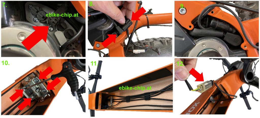
10. Führen Sie das in Schritt 4 bis 8 eingefädelte Kabel nun durch den Akku-Schacht nach oben. Achten Sie darauf, dass das Kabel beim Einsetzen des Akkus nicht im Weg ist. Falls notwendig können Sie Kabelbinder verwenden, um das Kabel zu fixieren.
11. Den 4-poligen Steckverbinder des eingezogenen Kabels können Sie nun mit dem entsprechenden Gegenstück am Modul verbinden. Auch hier sind die Stecker codiert und können nur richtig herum zusammengesteckt werden.
12. Entfernen Sie als nächstes die Kabeldurchführung, durch die das Kabel zum Display in den Rahmen geführt ist.
13. Trennen Sie die schwarze, runde Steckverbindung zum Display. Das Ende, das aus dem Rahmen durch die gerade entfernte Kabelführung kommt, kann in den Rahmen zurückgeschoben werden. Verbinden Sie dann im Inneren des Rahmens die beiden schwarzen, runden Steckverbinder des Moduls mit den gerade getrennten Steckverbindern des Displays. Am besten verbinden Sie dazu zuerst das in den Rahmen zurückgeschobene Kabel und führen dann den anderen Stecker am Modul durch die Öffnung der Kabeldurchführung nach außen und verbinden diesen mit dem Steckverbinder des Displays.
Wichtig: Wenn Sie eine Sigma Remote 500 zusammen mit einem Sigma View 1200 Display an Ihrem Rad verbaut haben, ist das Display und die Remote über ein Y-Kabel mit dem Motor verbunden. Das Modul muss dann zwischen Motor und diesem Y-Kabel angeschlossen werden, nicht zwischen Display und Remote!
Danach schrauben Sie die in Schritt 12 entfernte Kabeldurchführung wieder fest. Verstauen Sie das Tuning im oberen Bereich des Rahmens und schrauben Sie die in Schritt 9 entfernte obere Akku-Halterung wieder fest.
Aktivierung vom Tuning
Um die Unterstützung oberhalb von 25km/h an- oder abzuschalten, wechseln Sie bitte die Unterstützungsstufe um eine Stufe runter, hoch, runter und wieder hoch (- + - +). Bei Erfolg sehen Sie die Animation der Kapazitäts-Anzeige des Akkus wie beim Einschalten Ihres Pedelecs, die dadurch über den aktuellen Zustand informiert. Die Animation ist nur auf der Bedieneinheit zu sehen, nicht auf dem Display!
Ein Beispiel, beginnend in der Stufe 3:
Taster runter (neue Stufe: 2)
Taste hoch (neue Stufe: 3)
Taste runter (neue Stufe: 2)
Taste hoch (neue Stufe: 3)
Das Tuning zeigt eine kurze Animation über die Kapazitäts-Anzeige des Akkus an. Läuft die Kapazität von leer auf voll, unterstützt Sie Ihr Pedelec auch mit Motorleistung, wenn Sie schneller als 25 km/h fahren. Läuft die Anzeige von voll auf leer, endet die Unterstützung des Motors bei 25 km/h.